Motorized Bicycle Chain Tensioner Guide
Set up a motorized bicycle chain tensioner only after correcting sprocket alignment, chainline, chain length, wheel position, and secure mounting.
Table of Contents
- Diagnose before adding tension
- Isolate the engine before inspection
- Check chainline without the tensioner hiding it
- Find runout and the tight point
- Confirm chain identity and length
- Compare tensioner layouts by failure mode
- Set the approved tensioner
- Check the whole fault envelope
- Test and reinspect
- Immediate stop conditions
- Bottom line
A motorized-bicycle chain tensioner should manage the specified slack in an already compatible, aligned drive. It cannot fix a crooked rear sprocket, wrong chain, poor wheel position, loose engine, damaged parts, or unapproved frame mount. If the bracket could rotate into the spokes or tire, do not run the engine.
This is a research-based diagnostic guide, not a universal installation specification. Current search results emphasize generic products and forum instructions, including unsupported slack numbers. Use the exact kit, chain, sprocket, engine, wheel, and tensioner maker’s instructions instead.
Diagnose before adding tension
| Check | Continue when | Stop when |
|---|---|---|
| Engine and sprockets | Mounts are secure and sprockets are centered and aligned | Engine moves or a sprocket is bent, eccentric, loose, or wrongly oriented |
| Chain | Pitch, width, length, condition, and connecting method match | Chain binds, is damaged, mismatched, or needs excess roller deflection |
| Wheel | Axle is seated and retained; wheel runs true | Axle moves, wheel has play, rim or spokes are damaged |
| Tensioner | Exact design, anchor, roller, torque, and orientation are approved | Generic clamp needs drilling, crushing, or improvised anti-rotation |
| Clearance | Chain and bracket clear tire, spokes, brake, frame, cables, and guard | Any moving or loosened position can reach the wheel |
Start with the motorized bicycle guide when the frame, brake, wheel, tire, engine, or legal interfaces remain unresolved.
Isolate the engine before inspection
Work on a stable bicycle with the engine off and cool. Follow the system instructions to isolate fuel and ignition. Secure the spark-plug lead away from the plug where specified. Keep fingers, hair, clothing, and tools out of chains and sprockets.
Never adjust or observe a chain near a running engine. Hand rotation gives enough information to find alignment, runout, binding, and the tight point without exposing the mechanic to powered motion.
Check chainline without the tensioner hiding it
Stand behind the bicycle and sight along the engine sprocket, chain, rear sprocket, and any approved idler. The chain should approach and leave each sprocket in the same plane. A tensioner should not pull the chain sideways to create apparent alignment.
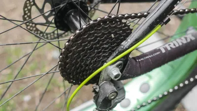
Check engine position, mount security, sprocket dish and orientation, rear-sprocket centering, lateral runout, wheel alignment, axle seating, and chainstay clearance. Correct the source of the angle. Do not stack unknown spacers, bend a bracket, or offset the roller as a shortcut.
Chainline is the first gate; tension comes later.
Find runout and the tight point
Rotate the rear wheel slowly through at least one complete revolution. Watch the rear sprocket edge against a fixed visual reference. Then watch the chain’s vertical movement in the free span.
Changing slack can come from an off-center sprocket, bent sprocket, uneven mount, wheel or shaft runout, bearing play, stiff link, or damaged tooth. Mark the tightest position for diagnosis. If the difference is substantial or the source is unknown, correct it before setting the roller.
Excess tension at the tight point can load bearings, shafts, and sprockets. Excess slack at another position can allow derailment. An idler cannot make an eccentric drive safe.
Confirm chain identity and length
Match chain pitch and width to both sprockets. Inspect every link for cracks, corrosion, stiff articulation, damaged rollers, distorted plates, and a correctly installed connecting link or pin. Replace a damaged chain rather than forcing it around a roller.
Set chain length by the kit instructions. Removing too few links can demand excessive tensioner travel. Removing too many can prevent assembly, overload the drive, or leave no adjustment range. Do not use the roller to consume a large loop that should have been removed through correct sizing.
Pitch wear and slack are different measurements. The chain-wear measurement guide covers wear checks for applicable bicycle chains; use the motor-drive chain maker’s limit for the engine side.
Compare tensioner layouts by failure mode
Clamp-on roller
A clamp-on roller is only as secure as its frame interface and anti-rotation design. A narrow clamp around a round stay can rotate under chain load. Use the exact bracket, saddle, hardware, orientation, torque, and frame location approved by the kit and frame makers.
Do not drill a stay or crush a tube. The bracket and roller must remain outside the wheel envelope even under the documented fault allowance. If loosening could put a bolt or roller into the spokes, reject the layout.
Arch or multi-point mount
An arch or multi-point design can reference more than one fixed location and resist rotation better. It still requires exact wheel, axle, frame, sprocket, tire, brake, and chain compatibility. More attachment points do not excuse a crooked chainline.
Engine or axle adjustment
Some systems set chain tension through engine position, rear-wheel position, or a dedicated dropout arrangement and do not call for an idler. Do not add a roller automatically. Extra parts can introduce another failure point and alter wrap or clearance.
Spring-loaded design
A spring can manage variation only when the system maker specifies it. Spring force, travel, chain span, wrap, guard, and failure position need documentation. A spring does not cure eccentric parts or insecure mounting.
Set the approved tensioner
Use the chain-slack range and measurement point from the exact system. Do not copy a one-inch or two-inch rule from a marketplace description or another engine kit.
The bounded sequence is:
- Isolate the engine and stabilize the bicycle.
- Verify engine, wheel, axle, and sprocket security.
- Correct sprocket alignment and runout.
- Fit the specified chain at the correct length.
- Seat and retain the rear wheel.
- Find the tightest point by hand rotation.
- Install the approved tensioner in its specified span and orientation.
- Align the roller with the chain plane.
- Tighten documented hardware to the exact torque and locking method.
- Rotate the wheel again and check slack, clearance, and hardware.
Do not invent a torque value. The bracket, fastener, frame interface, and thread condition determine it.
Check the whole fault envelope
Observe clearance through a complete wheel rotation. Include the tire’s true width, spoke path, brake movement, chain vibration allowance, roller edges, fastener ends, frame, cables, and chain guard.
Ask what happens if the approved fastener loses a small amount of preload. A safe design should not immediately swing a hard part into the wheel. This does not permit loose hardware; it tests whether the layout has a catastrophic single-point path.
The motorized-bicycle mag-wheel guide explains why the drive interface must match the exact wheel. The motorized tire guide covers rim fit, pressure, load, and nearby clearance.
Test and reinspect
Perform the initial static checks with the engine disabled. If the maker permits a powered test, use a controlled area away from traffic and bystanders. Begin at low speed and stop for noise, changing tension, rubbing, bracket movement, wheel movement, or altered brake feel.
Reinspect after the maker’s first test interval. Look for polished paint, clamp marks, loose hardware, leaning roller, chain-edge wear, sprocket movement, axle movement, tire contact, spoke contact, and debris around the guard. Repeat after wheel removal, chain service, an impact, or a derailment.
Immediate stop conditions
Stop riding for:
- bracket, roller, engine, sprocket, axle, or wheel movement;
- contact or impact marks at tire, spoke, brake, frame, or guard;
- chain derailment, stiff link, damaged roller, or cracked plate;
- hooked, chipped, bent, or loose sprocket teeth;
- substantial tension change during rotation;
- a roller leaning away from the chain plane;
- a crack, dent, gouge, or spreading at the mount;
- new vibration, rubbing, clicking, or grinding.
After a derailment, inspect the wheel, spokes, tire, brake, frame, chain, sprockets, engine mounts, and tensioner. Do not reinstall the chain and continue without finding the cause.
Bottom line
Use a motorized-bicycle chain tensioner only after alignment, sprocket runout, wheel retention, chain identity, and chain length are correct. Choose an exact approved mount that cannot rotate into the wheel, use documented torque and slack values, and stop at the first sign of movement. A second drive path adds a different problem; our jackshaft-kit guide explains that service burden.